I was asked in a tweet to touch on the topics of Etherpad and Security.
I initially wrote this post explaining how Etherpad handles Security etc. but then I figured I should a side by side comparison with Zoom because that’s the currently criticized product.
Etherpad is not perfect, it’s not a commercial product, it is commercially used by some large organizations but this is not a sales pitch. Etherpad is a community movement, it’s goal is not to provide shareholder value or increase profitability. It’s goal is to provide a collaboration tool used by anyone, anywhere without exception.
Let’s also be clear, other stella video conferencing tools exist, we love Jitsi for example, Etherpad’s functionality is no where near Jitsi for Video conferencing. Etherpad provides document editing and video conferencing in one package. If you just want video conferencing, Jitsi ( and other open source software exists ) are your ally.
Would I use Zoom for anything where privacy or safe guarding is a consideration? No.
Would I use it for chatting with my family? Yes.
Facebook privacy concerns
Does Etherpad have problems with Social platform integration? No, but there is a social plugin if people want to bring social elements in. That’s up to the site admin.
Malicious code silently being deployed
Does Etherpad install any non documented code on your machine? No. Everything is open source. Admins can install plugins which aren’t provided as a core part of Etherpad, a plugin could do something nefarious as we don’t run them sandboxed.
Side musing:
It’s worth noting noting Etherpad relies on thousands of dependencies, so it’s entirely plausible that one of those could inject malicious code into the software. To mitigate this we run security audits on release.
Github also provides ongoing dependency vulnerability monitoring so we’re constantly updating the software to resolve vulnerability related issues, usually 1 or so moderate a week and 1 critical a month.
That’s the honest truth about modern software, it’s vulnerable. It’s ALL vulnerable so you have a choice to use something that is honest about it’s vulnerabilities or hides behind the door of closed source providing an ignorance is bliss situation.
Does Etherpad’s video conferencing plugin (ep_webrtc) access your camera or any hardware without users permission? No. We use “getUserMedia” which is provided through the web browser so users permission is required.
Video call traffic and encryption
Can Etherpad be installed locally to avoid traffic leaving your site/school/premises? Yes. If you do host your own we recommend hosting your own TURN/STUN server too to ensure ALL data stays local.
There is something specifically worth mentioning for Educators. School firewalls and routing is complex. The 85% connectivity without TURN (so the amount that can go direct user to user[this is the best case scenario we have reached so far]) is with a lot of debugging and tweaking with US districts. The UK is yet to embrace this level of debugging, routing and because of this the 85% will likely start at 50% until schools / local authorities start deploying their own TURN servers to stop the traffic having to go external.
Is Peer to peer video connectivity the best way?
From a bandwidth perspective, mheh, ish, you hit issues with bandwidth with less users(but moving forward bandwidth will be increasing to meet this demand so p2p will win).
From a privacy perspective, yes.
From a functionality perspective, mheh, maybe, peer to peer connections are more difficult to establish than through a central service (hence the TURN/STUN) and if you have a central server you can negotiate and manage stream bandwidth depending on # of users. Zoom does what it does well, better than Etherpad. But where Etherpad shines is it’s transparency and flexibility. Let’s say you don’t want video and only want Audio? You can make that change. You have control as a user, developer, devops, manager etc.
What does the future look like?
Will Etherpad provide a commercial solution at some point? Probably not, we cherish our container partners dearly and we want them to be able to benefit from deploying Etherpad to clients and also let them care about scaling/deployment etc so we can focus on building the software. Lots of services exist that let you deploy Etherpad, docker is a thing, npm is a thing, git is a thing. You can even install Etherpad on Windows Server for the ultimate roller-coaster experience.
I contribute to a collaborative editor tool, Etherpad. It is excellent and really doesn’t get enough love from educators Vs Google and Microsoft’s offerings when I think it should.
Etherpad can be installed within 20 seconds. No technical knowledge required.
Etherpad is a relatively long running project, in fact Google used our operational transform engine in Google Docs and Microsoft ‘borrowed’ heavily for 365. Etherpad was the original web collaborative editor.
Etherpad is open source, built by a community, meaning we have complete transparency so if you get stuck or have an element you dislike, you can change it.
Etherpad is part of Software Freedom Conservancy which is a registered charity.
Etherpad wont change under you, Etherpad wont introduce a ribbon without the ability to disable it, Etherpad wont introduce a clippy without giving you a strong enough alcohol to banish it.
Etherpad can’t go bankrupt if an economy tanks.
Etherpad has way more educational resources than Google Docs / Microsoft 365. Plugins such as MathJax, Text Statistics (grading of quality of writing), Accessibility such as text to speech and it’s used by huge organizations (Wikimedia/UN) meaning Etherpad focuses heavily on localization and accessibility requirements such as Aria.
Etherpad’s video and audio calls are not centralized, removing the main flaw currently constraining Google during these trying times. Also when you are back in a school environment if you do video calls between departments the video feed will stay inside your environment removing bandwidth requirements / costs.
Etherpad can be hosted within your organization, even at home.
Etherpad doesn’t require any sign up, but various plugins exist if you want to have authentication to whatever mechanism you want and also for pad management. The world is your oyster.
Etherpad never loses document fidelity on export. Unlike Google docs and 365 when you take a document from Etherpad to another Etherpad instance no history of the document is lost. This means that any auditing for regulatory bodies is easy.
Phew, that’s a lot of reasons to consider trying Etherpad 🙂
I salute Google and Microsoft and tools like Jitsi and other educational tools for everything they do for Education. Etherpad is different from it’s core and allows those more directly involved in Education to be empowered without a dependency on commercial software.
This is a follow up post to a previous attempt at hacking the Peugeot Ion immobilizer. This is the success story, I will explain where I went wrong and how we solved the problem.
Before I get started I want to explain that by “Hacking” I mean gaining access to parts of the system that Mitsubishi usually tie down to their own infrastructure. I am not talking about a remote hack, denial of service or anything destructive. The purpose of this post is to inform and educate, any malicious, unkind, unfair or generally negative usage of this information is the choice of the reader. I provide no warranty and accept no liability.
First up, props to Fobfix again for doing pretty much all the work. I’m mostly a grunt here and he is the Wizard.
Devices required for VIN or Keypair change
The Ion/Miev has the key tables/values stored in 3 locations. The key (obviously), the ETACS and the ECU. The ETACS is what most people would call the Body Control Unit.
The Ion/Miev has the VIN stored in the Motor controller, ETACS, ECU. The Motor controller is the one here that trips most people up. Simply put, if you change the motor controller IE replace a faulty one, you will need to rewrite the VIN in the EEPROM. This is very unusual for manufacturers.
Dumping and Writing
To get a successful dump/write use the XGecu Pro with the chip set BR93H86(RF). At the time of completing this work we were using version 8.5
Using a different reader(actually we tried two) before was where we went wrong. The previous reader software and hardware had insufficient support for the BR93H86 chip. Before we were targeting the 93C86 which while similar is clearly different.
Modifications of contents
For modifications to the ROM contents use digitalkaos or another EEPROM car modification forum. They should be able to write the correct values with the corresponding checksum value.
In this post I’m going to document our attempts and ultimately our failure to clone a Mitsubishi i-Mievs Immobilizer system EEPROMs from one car to another. I will hopefully explain a bit about the security architecture and I will also my discoveries and some “pro tips” for not getting yourself in the same pickle as me. I appreciate most readers wont expect me to publish a failure story but a huge amount of time I spend working on projects is failure after failure, without writing the failures down myself and others could replicate the failure and that’s not a good path to progress.
The Peugeot Ion AKA Mitsubishi i-Miev & Citroen C-Zero is an electric car that was built for both Peugeot and Citroen by Mitsubishi motors. The car has a relatively standard security implementation. The vehicle we worked on had an industry standard RKE implementation. The remote locking part operating at the UK standard 433.92Mhz and the immobilizer implemented using the standard 125khz RFID “barrel ring” setup.
Contrary to popular understanding Mitsubishi do not include transponder data in a Body Control Unit (BCU). This is in contrast to Peugeot and Citroen who usually do. Do not think of the Ion or C-Zero as a Peugeot or Citroen, I have had countless offers of people saying they can help but not really understanding the entire car is built by Mitsubishi and as such any knowledge of other manufacturers implementations is irrelevant.
Background
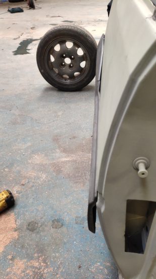
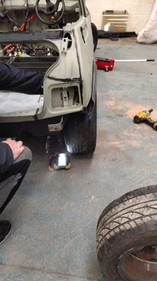
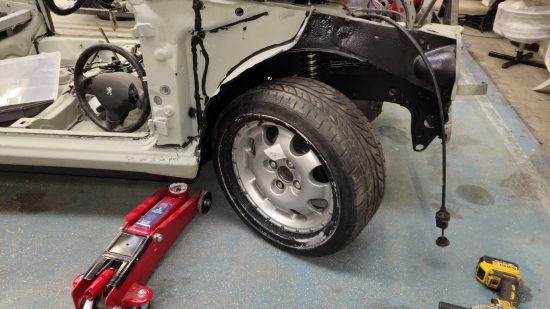
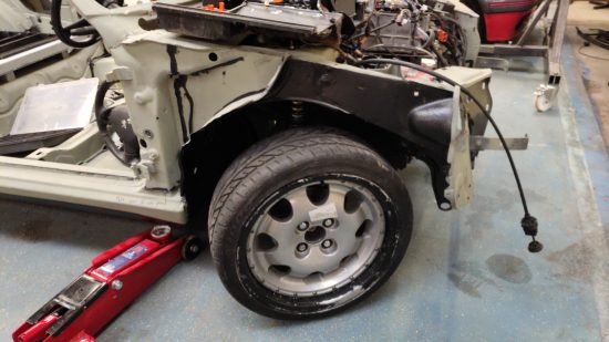
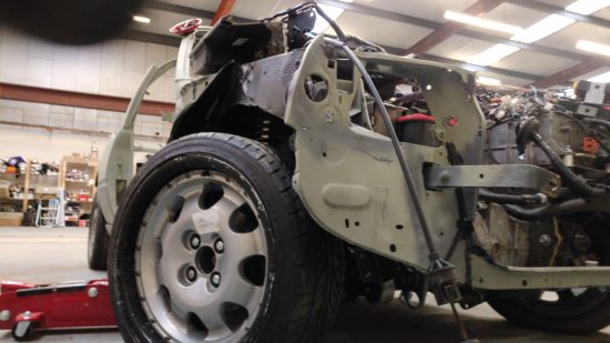
I am transplanting a written off Ion drive train, ignition barrel, batteries et al into a Peugeot 205. I had everything working after being stripped from the Ion then once I had transplanted the items into the 205 nothing worked. I could of course have bought an entirely new Electric drive train setup but my goal here was to learn from others and reuse existing electronics so avoid them landing in the scrap pile. I was able to pick up a damaged Ion for ~£2000 which is a fraction of the cost of an electric drive train and I was able to break the car for a decent return on my spend.
Debugging
After a serious amount of head scratching and ensuring each wire was properly reinstalled we decided to test the key. Actually it wasn’t even on our to-do list to check the key, nothing really pointed at the key failing but my buddy Duncan had an inclination it was at fault so took it to his lab to check it.
Duncan runs Fobfix and specializes in key repairs and programming so it was lucky I ran the problem past him. The key did show some signs of physical distress, at one point during the transplant the key was in the barrel and did experience some impact but I thought it was a negligible amount and not enough to cause a failure, especially not of the transponder internal the key.
We checked the Key two different ways, firstly we checked the 433Mhz RF characteristics and after this passed (we could see noise on an SDR) we tried to read the ID from the key using a standard RFID reader. The IC in the key is a commonly used NXP PCF7942. This family of IC’s incorporate an 125Khz RFID transponder and rolling code remote section all in a single IC.
After verifying the reader using another key that the reader was successfully obtaining an ID from another similar key we discovered that the Ion key was not providing an ID, this was a huge red flag. It is very rare that this type of IC fails at the silicon level. The RFID section of these fobs is made up of a simple LC resonant circuit so we checked that it wasn’t a dry solder joint, coil or resonant capacitor. Patching a known good IC into the LC circuit gave us an ID, patching the suspect IC into a know good LC circuit still failed so therefor we had no way to authenticate to the car.
The key is pretty normal, nothing new, it is just a transponder which stores key data that communicates through the antenna coil in the car barrel to the car.
With Tin Foil wrapping my cranium I would say that somehow my tinkering made the Ion nuke the key, why, I don’t know but perhaps I managed to get the car into some panic mode which decided to attempt to rewrite / blank the key data and then nuke it’s ability to communicate an ID. It’s highly unlikely Mitsubishi or the Key IC manufacturer would do this though, all of the car access control is handled by the EV ECU and ETACS so that’s where Mitsubishi would focus on providing protection.
Attacking
As we had lost our ability to authenticate to the vehicle with a key and had no ability to request Mitsubishi program a new key we were stuck between a rock and a hard place. This left us with only two options:
Option 1 was to purchase a key, ETACS and EV ECU from a breakers yard. We went ahead and did this and when the components arrived it was clear they were heavily water damaged and it would have been fruitless to use these. As no other units were available at breakers we decided to go for Option 2.
A side note here on buying car parts from eBay. I receive roughly 80% faulty/incorrect parts for cars.
Option 2 was to dump the Transponder Key Data and the EEPROM from the ETACS and EV ECU from a known working vehicle. Thankfully my buddy Ash had already offered his services when we explained the project to him. Ash has two 2012 i-Mievs, our recipient vehicle is an Ion but the EEPROM contents from the i-Miev should be transplant-able, theoretically…
To provide a starting point we used an aftermarket tool to clone the Hitag2 transponder in the i-Miev. The main security of the Hitag2 stream cipher is a 48 bit security of key used to seed the initial cipher state known as the ISK (Initial Secret Key). Once we had access to this ISK, it gave us a reference to search for in the dumps that we would be taking. We would also be looking for the specific transponder ID (32 bit).
Dumping the EV ECU EEPROM
The EV ECU is located under the rear seat. Removal and dumping the EV ECU was relatively simple. Using an EEPROM reader and targeting the IC “BR93H86” (Apparently a common 93C86 serial EEPROM variant)we were able to dump successfully and after bit flipping we could clearly see the car VIN. We repeated the dump process on Ashes i-Miev EV ECU and now had two successful EV ECU dumps. The ISK we retrieved from the cloning procedure was also identified in the dump. Interestingly the transponder Id wasn’t found in this dump.
Writing the EV ECU EEPROM
Writing the Ion EV ECU EEPROM was when things started getting problematic.. The EEPROM is Write protected and shifting the pin used for write protection to high didn’t make the IC writable. Only one thing for it, throw in some fly leads and a header and put a similar writable EEPROM on the board. This worked (we think) but without the correct data being on the ETACS we were not able to validate anything.
Dumping the ETACS EEPROM
The ETACS is buried in the drivers footwell / under the dash. It appears that the ETACS ECU handles the remote locking functions of the vehicle. Dumping the ETACS from the Ion was again pain free. We used the same process but this time targeted the Seiko S25A32. The Ion ETACS Part number is 8637A7.
Dumping the ETACS from the i-Miev was a problem. The EEPROM was flagged as “READ PROTECTED”. The actually EEPROM datasheet doesn’t include this functionality so this left us stuck. It appears that there may be a variant of this IC that has implemented some form of read protection, perhaps Ion doesn’t have it and i-Miev does? Perhaps somehow my Ion removed Read protection prior to me dumping it’s content?
The ETACS on the Ion and i-Miev do have different part numbers/model numbers but it was a real surprise to me that one would be read protected and one not. It’s unclear which models do/don’t have read protection but it’s worth documenting that 2012 Ion P/N 8637A7 did not have read protection but the 2012 i-Miev did.
Accepting failure
The read protection on the EEPROM made it too time expensive to continue with our Option 2 approach (dumping and cloning). I was forced back to Option 1, purchasing a key, matching ETACS and EV ECU. The EEPROM from the ETACS I needed to dump was from Ashes daily driver so I could only have the IC for a maximum of a few hours, shipping it to someone to investigate further was also not viable.
What we learned
With the EV ECU and ETACS both storing key immobilizer data it appears that somehow (further digging required) the barrel talks to the EV ECU and the EV ECU asks the ETACS unit to validate if the data is correct or not.. I assume the flow is like this:
1) Transponder enters field
2) Transponder handles challenge response with EV ECU through coil in barrel. It can do this as the EV ECU stores the ISK.
3) EV ECU asks ETACS if key ID value is in its whitelist table.4) ETACS responds with white/blacklist response.
One assumes that the reason for using two devices that are physically separated is to ensure that a thief can’t quickly brake into the vehicle, undo two 10mm bolts, swap out the ECU and then authenticate successfully. Remember the security of the barrel in modern cars is no longer the physical key, it is the challenge/response of the transponder. By making a thief change out two units it increases attack time from 30 seconds to ~5 minutes as the ETACS has two 10mm bolts but also 10 or so connectors that are difficult to access without some gymnastics. It is common in modern cars to have key data stored in two physical locations, I have to admit, it’s actually a pretty good idea/design.
I am not impressed with read and write protected EEPROM. If you have the ETACS and EV ECU out and EEPROMs off the PCB you have been able to physically attack the car for at least an hour and have access to a decent chunk of bench based equipment. I’m of the opinion read and write protection of EEPROMs are just overkill and only really stops people like me re-purposing the equipment — Right to repair ‘n all that.
The key data is not stored in the other obvious place, the Battery Control Unit. In all honesty I could have known this from further reading of the i-Miev workshop manual. It makes sense it’s not with the BCU as the BCU and EV ECU are mounted together to attacking and replacing both would be quick.
Avoiding this problem in the future
For future EV conversions I will ensure I create additional keys as back ups. If I had simply spent £20 on another key and used the internal to car process to add the new key I would have had an insurance policy should I lose a key or it fails.
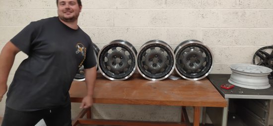
Making custom two-piece wheels is a lengthy process so in this post I’m going to brake it down step by step and provide a hopefully handy reference guide for you to make your own.
DISCLAIMER: I am by no way warrantying or providing any form of guarantee, advice or even suggesting you should build these wheels. These wheels will absolutely not be road worthy and are purely for show purposes only.
In this post I will be focusing on putting Peugeot 15″ 205/309 1.9 GTi Speedline faces into BMW 17″ Split Rims Barrels but the process should be the same for most cars. As per the previous disclaimer: Anything you build is your responsibility and I am not liable for any damages or harm caused by you tinkering. Still, that said, tinker on brother =D.
Things you will need.
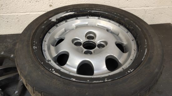
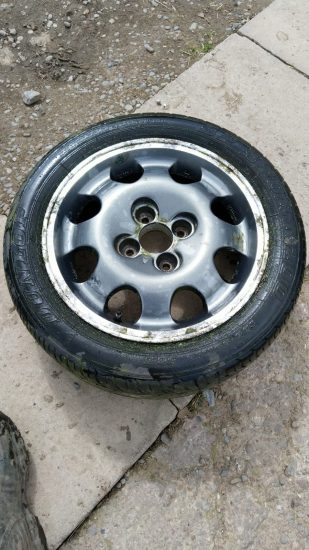
Peugeot 205/309 GTi 15″ wheels (ideally 5 but 4 will do it), wheels must be tyre free.
BMW E39 17″ wheels (ideally 5 but 4 will do it), wheels must be tyre free.
A water jet or friend with a water jet.
A plasma cutter or friend with a plasma cutter.
A friendly local machinist (with a lathe & CNC mill)
A friendly local shot blaster, powder coater
*Optional: A friendly local diamond cut / clear coat guy.
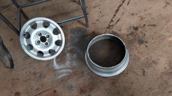
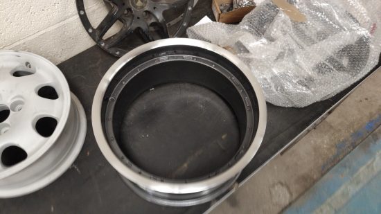
Remove the tyres (if any) and remove the inner section from the BMW wheels. Send all of the wheels to be acid dipped / stripped. This will cost around £20 per wheel so in this case we’re doing 10 wheels so roughly £200..
Plasma torching the 205/309 (inner) wheels and turning down the rough edge.
Plasma torching is the process of cutting the face off the barrel. It takes about 15/20 minutes per wheel. One thing to be VERY careful of is the slag which will exit the cut point and can easily splatter the face of the wheel causing additional work later. To resolve this keep a wet rag on the opposite face of the rim of which you are cutting.
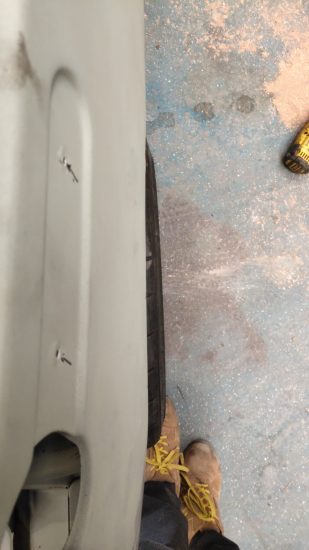
Marking the wheel ready to be cut
Step 1 is marking each wheel with the cut point, here you can see the cut point in red marker.
Step 2 is preparing the wheel by placing it on the wheel and putting aforementioned rag on the opposite side of the cut.
Step 3 is slowly cutting the wheel with a plasma torch.
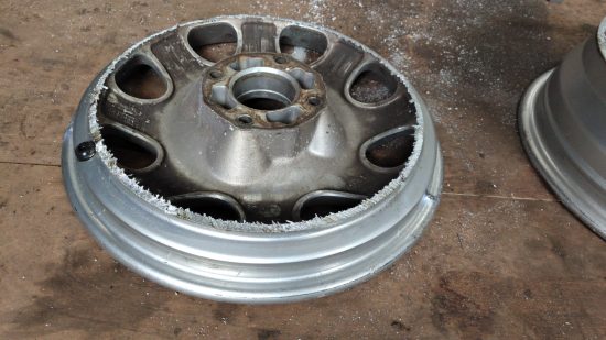
Face cut away from barrel
But why not turn this off on a lathe with a cutting bit? The reason this is a bad idea is you will need to hold both the face and barrel with a chuck and most lathes only have one large chuck. When the face leaves the barrel you would be left with a lot of material wanting to leave the face so it’s just easier to plasma now, remove the mass then turn after.
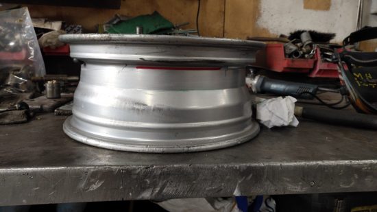
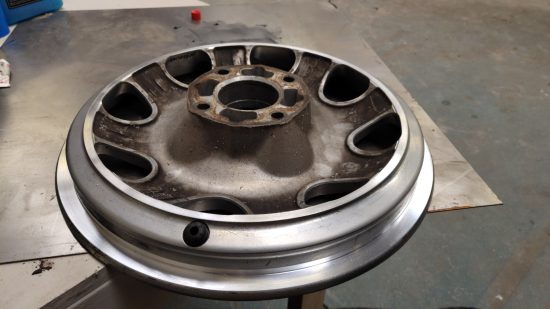
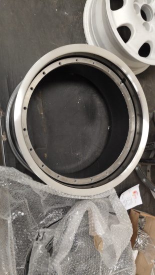
Rough inner edge after plasma torchingTurned down inner edge
As per above we turn down both the inner face but also the inside of the outer lip. We turn down the inner face just to make the edge safe to work with and clean. we turn down the inside of the outer lip to ensure our spacer will fit.
It should take about 10 minutes per wheel plus setup time to face off the wheels.
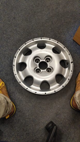
Assuming your 205/309 wheels are in good condition these can now go to the machinist ready for hole drilling and counter-boring.
Designing the spacer, hole and counter bore locations.
No holes or counter-boring on 205 wheels
The 205 inner faces won’t go directly onto the BMW wheels because there are no holes in the face. To put the holes in we’re going to need a machinist and the machinist is going to need a reference file. Machinists mostly work with solidworks files aka DXF. Thankfully you don’t need solid works to make these files, you can use free software called Inkscape.
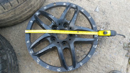
Basically in Inkscape you will need to make a hoop shape and place the bolt holes and counter bores on different layers. I’m not going to cover the whole process in this blog post but if you want the Inkscape SVG I used then feel free to email me and I will forward it over. That said, your machinist might like files in different formats so it’s critical you speak with them first to see how they want the data. For me I used a robot arm to get exact measurements of bolt locations and hole sizes but this could easily be done using a set of vernier or even a ruler.
Taking measurements with Vernier
Once you have your design I highly recommend creating your spacer next. The whole process of designing your spacer should be about 3 hours of labor.
Water jetting your spacer
It is a very good idea to start with scrap/sample pieces before going to Aluminum. For these wheels you will be using 1M x 1M of 10mm aluminum which isn’t cheap, I think for me it was about £250.
Scrap mild steel spacers
I ran my first samples in scrap 2mm mild steel. It took me about 6 revisions to get the holes in the correct location, the correct size and to decide on the depth of the spacer. Thankfully I have a local water jet machine so it wasn’t too time consuming. Once I was happy with my design I was comfortable passing the same DXF over to the machinist for drilling and counter-boring. A cut in 10mm aluminium should take about 40 minutes, expect to pay about £30 per hour of water jet time and probably £40 per hour of labor if you require someone to set the job up for you, handle your material and clean the piece after cutting. Do bare in mind that your spacer depth modifies the offset the wheels on the car. Increasing your spacer depth reduces your offset, we found 10mm was the happy medium for putting these wheels back on 205/309 et al, your mileage will vary! Don’t forget that if you change the depth of your spacers you will need different fitting lengths.
I only zinc primed the spacers because they aren’t visible.
Drilling and Counter-boring your inner wheels
Your machinist will want a DXF with two tool paths. One for the holes and one for the counter-bores. I usually just put them on different layers and in different colors in inkscape then export them. You might want to do this on your 5th wheel, which will be your test/sample/scrap if you get it wrong wheel. A decent machinist will need about an hours setup time and 30 minutes per wheel. Usual machinist and machine time is about 40 GBP so your holes/counter bores should cost around 200 GBP.
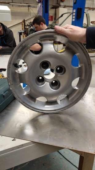
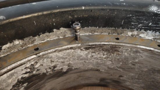
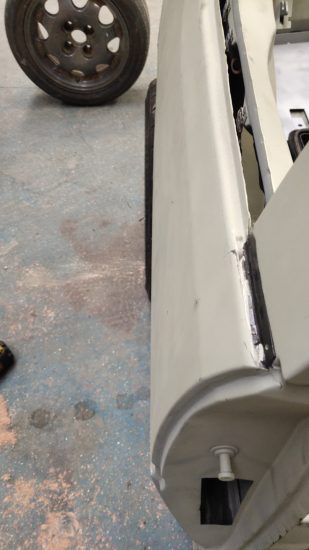
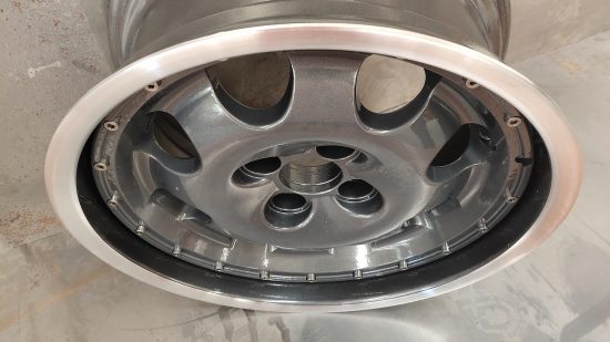
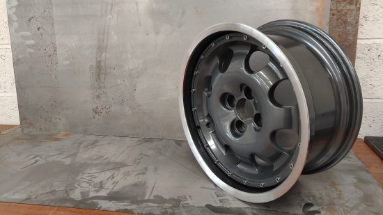
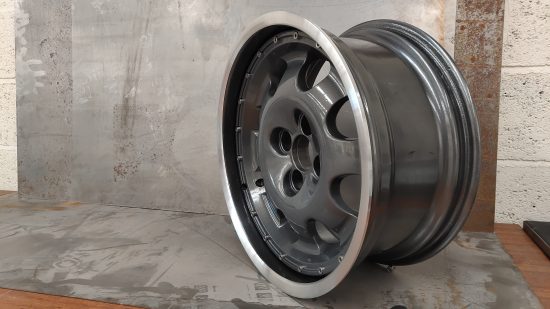
Checking the inner in the outer.
Testing the fitment.
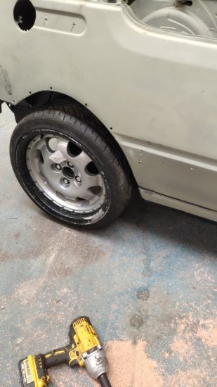
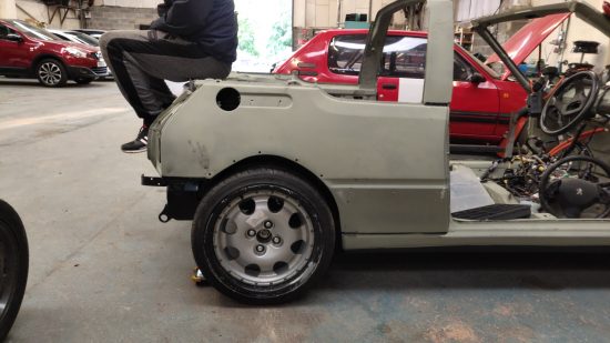
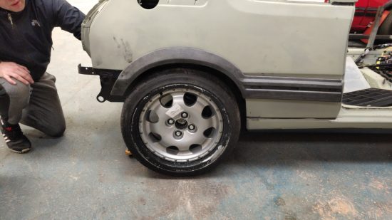
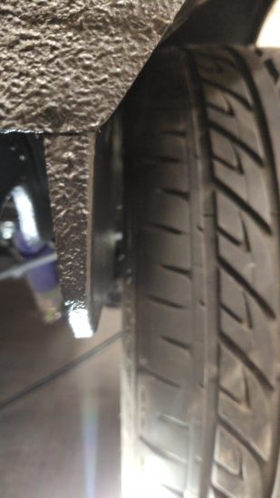
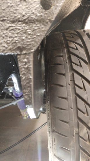
Now you have your inner and outer prepared you can offer them up together and ensure all holes line up. Also take this opportunity to test your M7 socket cap bolt fittings. Once I had the wheel assembled I asked a local tyre company to put a scrap 205 40 tyre onto the outer rim and then I was able to test fitment on a car.
It’s important when test fitting to ensure the wheels sits within the arch without any rubbing on the inner arch but also that you can achieve full lock. Also the 205s often rub on the rear so check the rear by having a mate jump up on and down on the rear boot and ensure it doesn’t touch anywhere. I’m lucky because I have a lot of 205s I can test with all at different ride heights. I found that these wheels fit nicely at 30mm drop but will probably require some rear arch modification (as per the norm of running 205 40 on a 205).
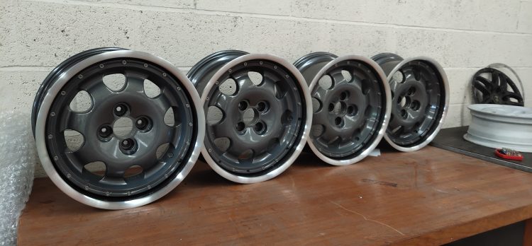
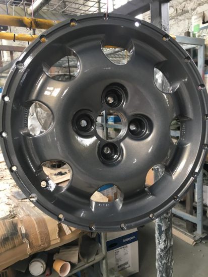
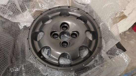
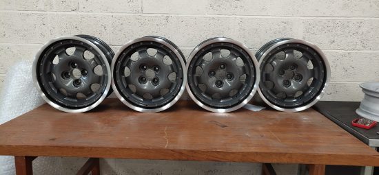
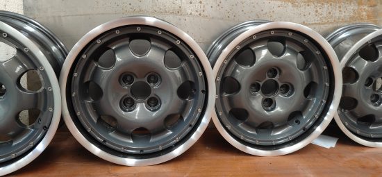
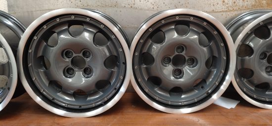
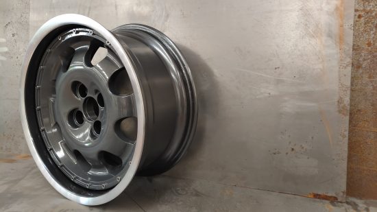
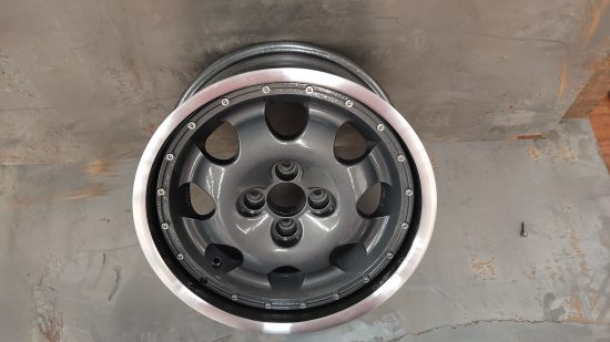
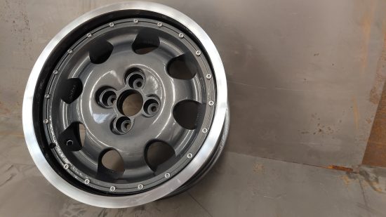
Making them pretty!
The Goodwood is a famous wheel within Peugeot circles
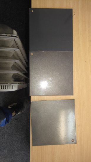
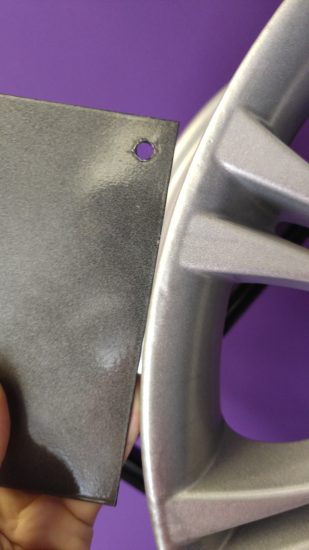
Next step is deciding on a design/color and getting them done! Firstly we decided on a color scheme, in this instance we settled on Goodwood. Goodwood wheels provide an interesting challenge because they have a silver/diamond cut outer rim and the rest of the rim is anthracite gray.
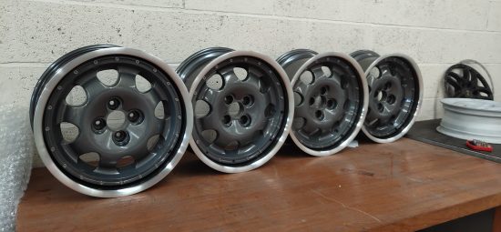
Not all grays are equal…
Initially our plan was to do the entire outer barrel in bright silver and the inners in anthracite but we don’t like making our lives too easy and we thought the additional anthracite on the outer barrel would additional depth (which is something I like). I intended to photoshop examples but I was too time invested already in this project so just decided to go for the diamond cutting instead.
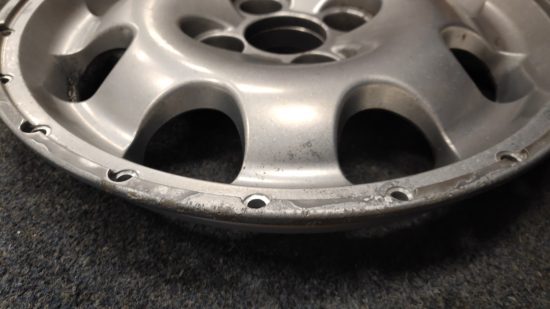
Before we could send the wheels to the powder coater we had to do some wheel repair. Thankfully my local friendly machinist was able to do some aluminium welding and then grinding down to fix a very badly damaged edge. This took about 2 hours work.
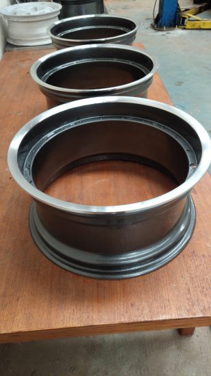
Once all repairs were done and we had decided on color we went to the local powder coating shop with all the parts and started to get pictures back of the bits as they went through their shop.
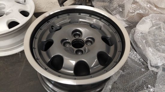
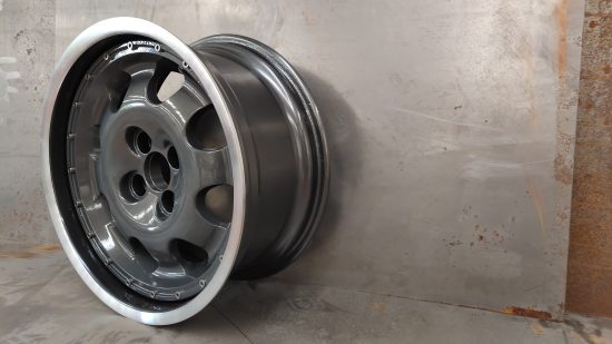
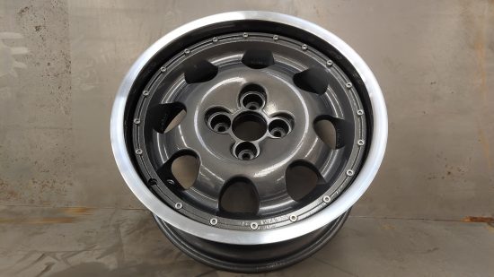
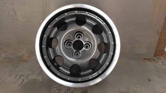
Powder coated inner
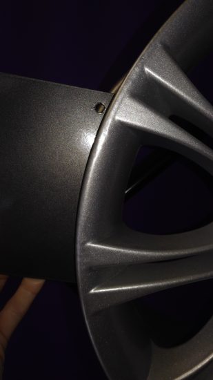
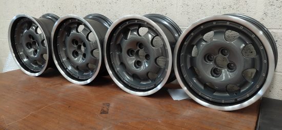
I used the same powder coating place to coat all inner and outer pieces but used a different shop for diamond cutting and clear coating the inners.
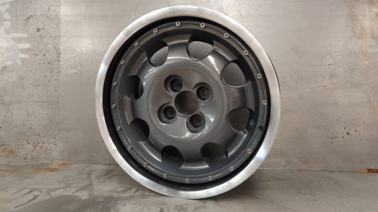
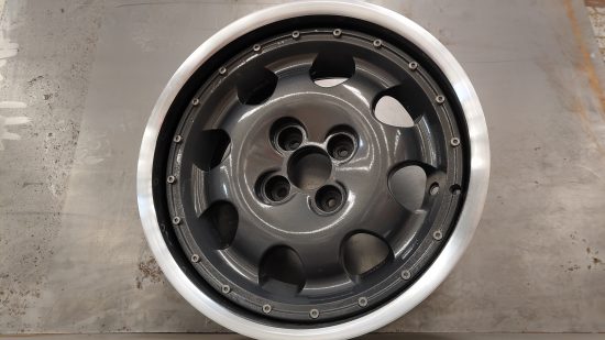
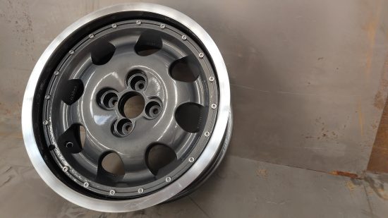
One thing you can spot close up is that there is no definite/exact line for where the diamond cutting ends. This is caused by me asking the diamond cutters to remove as little material as possible and also because normally when you diamond cut a wheel you have an exact face to work the bit to. With these outer wheels the face curves into the barrel wall so it’s hard to get an exact location to stop turning at. You have probably already established that Diamond cutting these wheels caused significant complications!
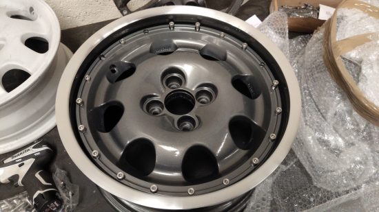
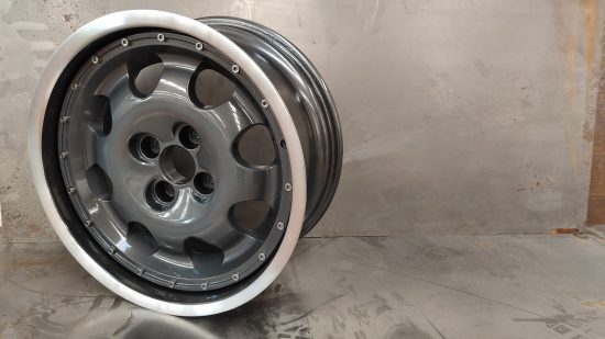
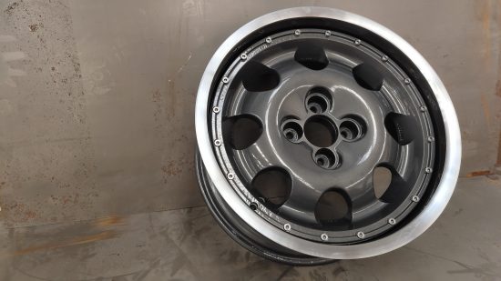
Assembly.
After such a long road I was happy to get through to assembly..
Assembly involved placing the spacers in the outer barrel, placing the inners on the spacers and installing the M7 fittings. Next step is to get them boxed up and take them up to my brother for fitment on his 309 Goodwood 🙂
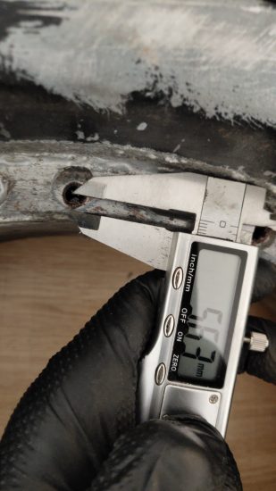
Just as a side note at this point: I made the mistake of measuring the entire bolt length and ignored the taper on the bolt where there was no thread. This lead to me getting the wrong size bolts. The actual holes in the base rim have an additional cavity for the center shaft of the bolt and this cavity does not have thread but does have material so you can’t put in a normal bolt. So my learning here is to measure only the thread length of the original bolt and add 10mm to that, don’t measure the entire bolt length.
Rough cost brake down
All costs in GBP. This makes assumptions no labour is free. All costs are estimates/rough and will vary depending on your relationships w/ your machinists and suppliers. Labor is estimated at ~£40 per hour.
Spacer Aluminium: £250 Wheel repairs: £200 Water Jet: £200 Test fitting: £80 Final assembly: £200 Plasma cutting Peugeot wheel: £80 Shot Blasting: £100 Powder coating (Due to special powder and 8 parts): £400 Diamond Cut (4 wheels): £300 Fittings (M6 bolts): £211.68 Primer: £5 CNC Machine Time & Machinist: £500 Lathe Time & Machinist: £100 Running between suppliers: £200
Total cost: £2,635.68
Things I learned and Summary.
I learned a lot during the process.
It’s important to use a wet rag when plasma torching. If you don’t it will require additional shot blasting / cleaning up of the inners.
Wet clear will give anthracite a very different finish to non-wet clear. I would use the same shop for coating/cutting/clear coating in the future.
Inkscape is funny when it comes to mechanical drawings. Make sure you are using Display > Outline. Don’t use stroke. Make sure you use correct layers when exporting for water jetting IE don’t water jet your counter bores when sending for water jet but do when sending for CNCing!
It’s important to start with a relatively good set of wheels (both) because any damage will need to be repaired before paint.
This process is expensive and time consuming to do.
To conclude, I have completed engine swaps which have been easier jobs than this. It’s a very expensive and quite consuming way to create custom wheels and to be honest, going straight to China for forged custom wheels might just be cheaper and easier! That said, this method does give retro cars the ability to keep their original styling while being able to put more rubber down on the tarmac.
Q&A
Are the wheels lighter? I’m not sure.
Are the wheels safer? No!
Would you do something like this for me? Yes. But I would want suitable compensation, something close to £1.5k per wheel for a project using the same inner/outer and it would be more for a fully custom project.
Could you do it without the diamond cutting? Yes and it would reduce that cost/complexity.
Did you have to order anything twice because you got it wrong? Yes, the fittings I originally ordered 40, then 30 then 25mm. Thankfully I only ordered a few 40s then by mistake 100 30’s then I finally settled on 25mm.. While 30mm will work in some holes not all holes on the BMW wheels were equal so I had to drop 5mm of thread. Because these wheels are not for driving on I figured that was fine.
Why not just order M7 28mm or something then if they were just a few mm long? Well firstly, you can’t get weird size M7s.. Secondly, it wasn’t the depth that was the issue, it was the final part of the original bolts which had no thread and were just used to located themselves in the hole. The GWR fittings didn’t have this pattern and as such wanted to thread too far into the wheel causing the thread to get damaged and in some cases (this really screwed me over) the fixings would get stuck in the rim only for me to have to angle grind them off.
Did I bodge anything? Yes. On one wheel 3 of the heads of the bolts are fake.
Did I finish them completely with center caps etc? No. I totally forgot about center caps until I wrote this blog post =D.